Adapted from Sparkfun Inventor Kit Experiential Guide
Introduction
Now we are going to step into the world of ICs (integrated circuits). In this circuit, you’ll learn all about using a shift register (also called a serial-to-parallel converter). The shift register will give your RedBoard or Arduino Uno R3 an additional eight outputs, using only three pins on your board. For this circuit, you’ll practice by using the shift register to control eight LEDs.
Parts Needed
You will need the following parts:
- 1x Breadboard
- 1x RedBoard or Arduino Uno
- 8x LEDs
- 8x 330Ω Resistors
- 1x Shift Register 8-Bit - 74HC595
- 19x Jumper Wires
Suggested Reading
Before continuing on with this experiment, we recommend you be familiar with the concepts in the following tutorial:
Hardware Hookup
Ready to start hooking everything up? Check out the Fritzing diagram below, to see how everything is connected.
| Polarized Components | Pay special attention to the component’s markings indicating how to place it on the breadboard. Polarized components can only be connected to a circuit in one direction. |
For the shift register, align notch on top, in-between “e1” and “f1” on the breadboard. The notch indicates where pin 1 is.
Fritzing Diagram for RedBoard
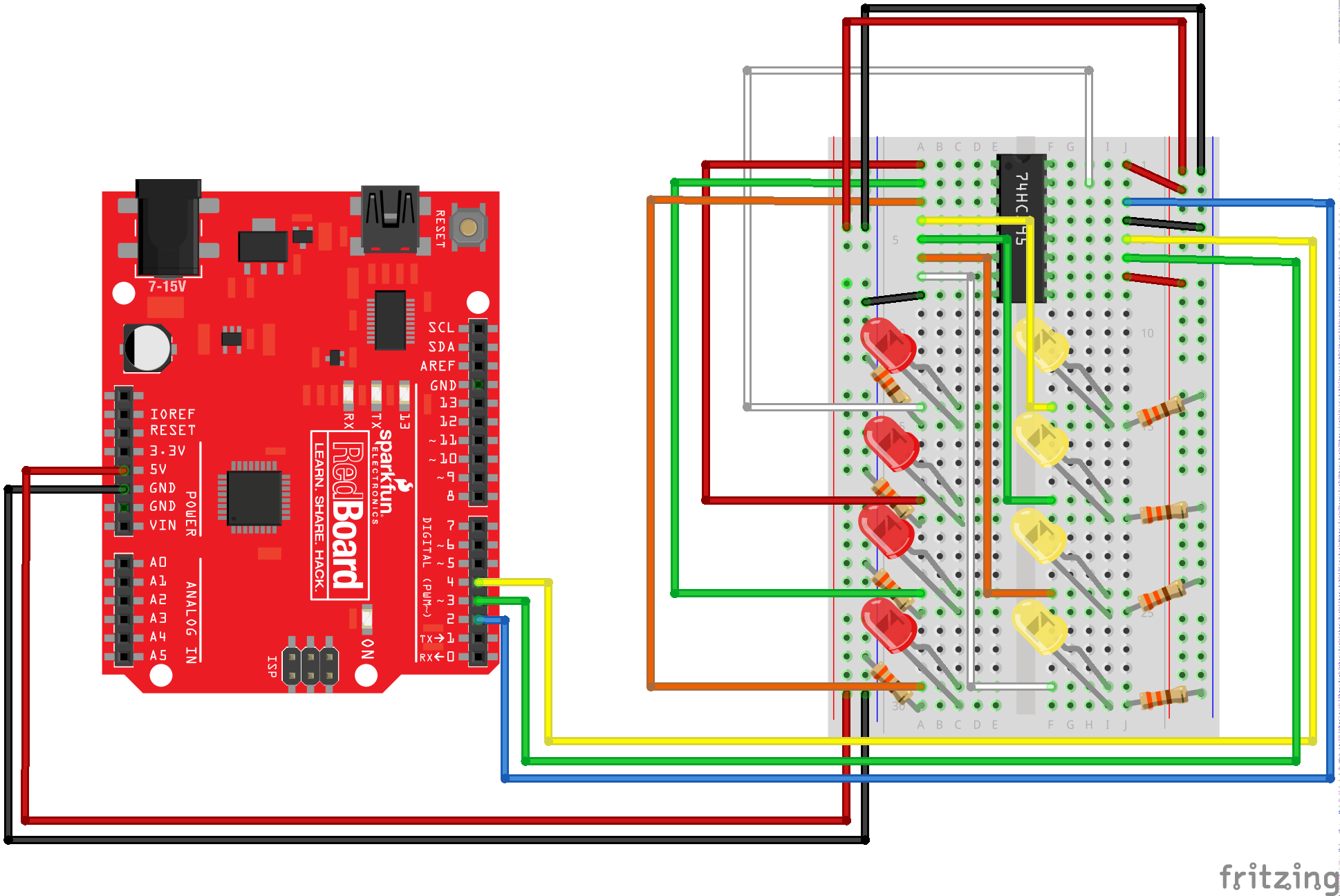
Having a hard time seeing the circuit? Click on the Fritzing diagram to see a bigger image.
Run the Sketch
/*
SparkFun Inventor's Kit
Example sketch 14

SHIFT REGISTER

  Use a shift register to turn three pins into eight (or more!)
  outputs

  An integrated circuit ("IC"), or "chip", is a self-contained
  circuit built into a small plastic package. (If you look closely
  at your Arduino board you'll see a number of ICs.) There are
  thousands of different types of ICs available that you can use
  to perform many useful functions.

  The 74HC595 shift register in your kit is an IC that has eight
  digital outputs. To use these outputs, we'll use a new interface
  called SPI (Serial Peripheral Interface). It's like the TX and
  RX you're used to, but has an additional "clock" line that
  controls the speed of the data transfer. Many parts use SPI
  for communications, so the Arduino offers simple commands called
  shiftIn() and shiftOut() to access these parts.

  This IC lets you use three digital pins on your Arduino to
  control eight digital outputs on the chip. And if you need
  even more outputs, you can daisy-chain multiple shift registers
  together, allowing an almost unlimited number of outputs from
  the same three Arduino pins! See the shift register datasheet
  for details:

  http://www.sparkfun.com/datasheets/IC/SN74HC595.pdf

Hardware connections:

  Shift register:

    Plug in the chip so it bridges the center "canyon"
    on the breadboard.

    The shift register has 16 pins. They are numbered
    counterclockwise starting at the pin 1 mark (notch
    in the end of the chip). See the datasheet above
    for a diagram.

    74HC595 pin     LED pin     Arduino pin

    1  (QB)     LED 2 +
    2  (QC)     LED 3 +
    3  (QD)     LED 4 +
    4  (QE)     LED 5 +
    5  (QF)     LED 6 +
    6  (QG)     LED 7 +
    7  (QH)     LED 8 +
    8  (GND)                GND

    9  (QH*)
    10 (SRCLR*)             5V
    11 (SRCLK)              Digital 3
    12 (RCLK)               Digital 4
    13 (OE*)                GND
    14 (SER)                Digital 2
    15 (QA)     LED 1 +
    16 (VCC)                5V

  LEDs:

    After making the above connections to the positive (longer)
    legs of the LEDs, connect the negative side (short lead) of
    each LED to a 330 Ohm resistor, and connect the other side
    of each resistor to GND.

This sketch was written by SparkFun Electronics,
with lots of help from the Arduino community.
This code is completely free for any use.
Visit http://learn.sparkfun.com/products/2 for SIK information.
Visit http://www.arduino.cc to learn about the Arduino.

Version 2.0 6/2012 MDG
*/


// Pin definitions:
// The 74HC595 uses a type of serial connection called SPI
// (Serial Peripheral Interface) that requires three pins:

int datapin = 2;
int clockpin = 3;
int latchpin = 4;

// We'll also declare a global variable for the data we're
// sending to the shift register:

byte data = 0;


void setup()
{
  // Set the three SPI pins to be outputs:

  pinMode(datapin, OUTPUT);
  pinMode(clockpin, OUTPUT);
  pinMode(latchpin, OUTPUT);
}


void loop()
{
  // We're going to use the same functions we played with back
  // in circuit 04, "Multiple LEDs", we've just replaced
  // digitalWrite() with a new function called shiftWrite()
  // (see below). We also have a new function that demonstrates
  // binary counting.

  // To try the different functions below, uncomment the one
  // you want to run, and comment out the remaining ones to
  // disable them from running.

  oneAfterAnother();      // All on, all off

  //oneOnAtATime();       // Scroll down the line

  //pingPong();           // Like above, but back and forth

  //randomLED();          // Blink random LEDs

  //marquee();

  //binaryCount();        // Bit patterns from 0 to 255
}


void shiftWrite(int desiredPin, boolean desiredState)

// This function lets you make the shift register outputs
// HIGH or LOW in exactly the same way that you use digitalWrite().

// Like digitalWrite(), this function takes two parameters:

//    "desiredPin" is the shift register output pin
//    you want to affect (0-7)

//    "desiredState" is whether you want that output
//    to be HIGH or LOW

// Inside the Arduino, numbers are stored as arrays of "bits",
// each of which is a single 1 or 0 value. Because a "byte" type
// is also eight bits, we'll use a byte (which we named "data"
// at the top of this sketch) to send data to the shift register.
// If a bit in the byte is "1", the output will be HIGH. If the bit
// is "0", the output will be LOW.

// To turn the individual bits in "data" on and off, we'll use
// a new Arduino commands called bitWrite(), which can make
// individual bits in a number 1 or 0.
{
  // First we'll alter the global variable "data", changing the
  // desired bit to 1 or 0:

  bitWrite(data,desiredPin,desiredState);

  // Now we'll actually send that data to the shift register.
  // The shiftOut() function does all the hard work of
  // manipulating the data and clock pins to move the data
  // into the shift register:

  shiftOut(datapin, clockpin, MSBFIRST, data);

  // Once the data is in the shift register, we still need to
  // make it appear at the outputs. We'll toggle the state of
  // the latchPin, which will signal the shift register to "latch"
  // the data to the outputs. (Latch activates on the high-to
  // -low transition).

  digitalWrite(latchpin, HIGH);
  digitalWrite(latchpin, LOW);
}


/*
oneAfterAnother()

This function will light one LED, delay for delayTime, then light
the next LED, and repeat until all the LEDs are on. It will then
turn them off in the reverse order.
*/

void oneAfterAnother()
{
  int index;
  int delayTime = 100; // Time (milliseconds) to pause between LEDs
                       // Make this smaller for faster switching

  // Turn all the LEDs on:

  // This for() loop will step index from 0 to 7
  // (putting "++" after a variable means add one to it)
  // and will then use digitalWrite() to turn that LED on.

  for(index = 0; index <= 7; index++)
  {
    shiftWrite(index, HIGH);
    delay(delayTime);
  }

  // Turn all the LEDs off:

  // This for() loop will step index from 7 to 0
  // (putting "--" after a variable means subtract one from it)
  // and will then use digitalWrite() to turn that LED off.

  for(index = 7; index >= 0; index--)
  {
    shiftWrite(index, LOW);
    delay(delayTime);
  }
}


/*
oneOnAtATime()

This function will step through the LEDs, lighting one at at time.
*/

void oneOnAtATime()
{
  int index;
  int delayTime = 100; // Time (milliseconds) to pause between LEDs
                       // Make this smaller for faster switching

  // step through the LEDs, from 0 to 7

  for(index = 0; index <= 7; index++)
  {
    shiftWrite(index, HIGH);    // turn LED on
    delay(delayTime);       // pause to slow down the sequence
    shiftWrite(index, LOW); // turn LED off
  }
}


/*
pingPong()

This function will step through the LEDs, lighting one at at time,
in both directions.
*/

void pingPong()
{
  int index;
  int delayTime = 100; // time (milliseconds) to pause between LEDs
                       // make this smaller for faster switching

  // step through the LEDs, from 0 to 7

  for(index = 0; index <= 7; index++)
  {
    shiftWrite(index, HIGH);    // turn LED on
    delay(delayTime);       // pause to slow down the sequence
    shiftWrite(index, LOW); // turn LED off
  }

  // step through the LEDs, from 7 to 0

  for(index = 7; index >= 0; index--)
  {
    shiftWrite(index, HIGH);    // turn LED on
    delay(delayTime);       // pause to slow down the sequence
    shiftWrite(index, LOW); // turn LED off
  }
}


/*
randomLED()

This function will turn on random LEDs. Can you modify it so it
also lights them for random times?
*/

void randomLED()
{
  int index;
  int delayTime = 100; // time (milliseconds) to pause between LEDs
                       // make this smaller for faster switching

  // The random() function will return a semi-random number each
  // time it is called. See http://arduino.cc/en/Reference/Random
  // for tips on how to make random() more random.

  index = random(8);    // pick a random number between 0 and 7

  shiftWrite(index, HIGH);  // turn LED on
  delay(delayTime);     // pause to slow down the sequence
  shiftWrite(index, LOW);   // turn LED off
}


/*
marquee()

This function will mimic "chase lights" like those around signs.
*/

void marquee()
{
  int index;
  int delayTime = 200; // Time (milliseconds) to pause between LEDs
                       // Make this smaller for faster switching

  // Step through the first four LEDs
  // (We'll light up one in the lower 4 and one in the upper 4)

  for(index = 0; index <= 3; index++)
  {
    shiftWrite(index, HIGH);    // Turn a LED on
    shiftWrite(index+4, HIGH);  // Skip four, and turn that LED on
    delay(delayTime);       // Pause to slow down the sequence
    shiftWrite(index, LOW); // Turn both LEDs off
    shiftWrite(index+4, LOW);
  }
}


/*
binaryCount()

Numbers are stored internally in the Arduino as arrays of "bits",
each of which is a 1 or 0. Just like the base-10 numbers we use
every day, The position of the bit affects the magnitude of its
contribution to the total number:

Bit position   Contribution
0              1
1              2
2              4
3              8
4              16
5              32
6              64
7              128

To build any number from 0 to 255 from the above 8 bits, just
select the contributions you need to make. The bits will then be
1 if you use that contribution, and 0 if you don't.

This function will increment the "data" variable from 0 to 255
and repeat. When we send this value to the shift register and LEDs,
you can see the on-off pattern of the eight bits that make up the
byte. See http://www.arduino.cc/playground/Code/BitMath for more
information on binary numbers.
*/

void binaryCount()
{
  int delayTime = 1000; // time (milliseconds) to pause between LEDs
                        // make this smaller for faster switching

  // Send the data byte to the shift register:

  shiftOut(datapin, clockpin, MSBFIRST, data);

  // Toggle the latch pin to make the data appear at the outputs:

  digitalWrite(latchpin, HIGH);
  digitalWrite(latchpin, LOW);

  // Add one to data, and repeat!
  // (Because a byte type can only store numbers from 0 to 255,
  // if we add more than that, it will "roll around" back to 0
  // and start over).

  data++;

  // Delay so you can see what's going on:

  delay(delayTime);
}
Code To Note
shiftOut(datapin, clockpin, MSBFIRST, data);
You’ll communicate with the shift register (and a lot of other parts) using an interface called SPI, or Serial Peripheral Interface. This interface uses a data line and a separate clock line that work together to move data in or out of the Arduino at high speed. The MSBFIRST parameter specifies the order in which to send the individual bits, in this case we’re sending the Most Significant Bit first.
bitWrite(data, desiredPin, desiredState);
Bits are the smallest possible piece of memory in a computer; each one can store either a “1” or a “0”. Larger numbers are stored as arrays of bits. Sometimes we want to manipulate these bits directly, for example now when we’re sending eight bits to the shift register and we want to make them 1 or 0 to turn the LEDs on or off. The Arduino has several commands, such as
bitWrite(), that make this easy to do.What You Should See
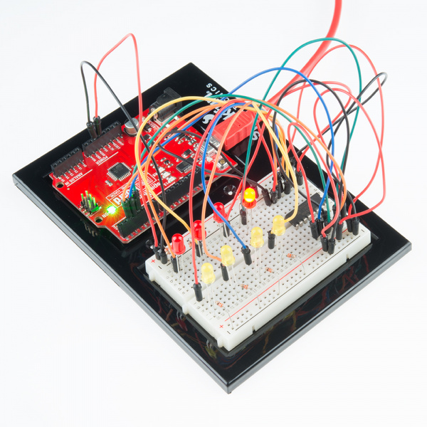
You should see the LEDs light up similarly to experiment 4 (but this time, you’re using a shift register). If they aren’t, make sure you have assembled the circuit correctly and verified and uploaded the code to your board. See the troubleshooting section.
Real World Application
Similar to experiment 4, a scrolling marquee display delivers a message with multiple LEDs. Essentially the same task the shift register achieves here in experiment 14.
Troubleshooting
The Arduino’s power LED goes out
This happened to us a couple of times, it happens when the chip is inserted backward. If you fix it quickly nothing will break.
Not Quite Working
Sorry to sound like a broken record but it is probably something as simple as a crossed wire.
Going Further
In the sample sketch above the initial light pattern that is demonstrated come from the function oneAfterAnother(). There are other functions, which are commented out, that you can try:
- //oneOnAtATime(); // Scroll down the line
- //pingPong(); // Like above, but back and forth
- //randomLED(); // Blink random LEDs
- //marquee();
- //binaryCount(); // Bit patterns from 0 to 255
To try out one of the other patterns use the "//" to comment out the oneAfterAnother() then remove the "//" in front of the function you want to try. Next be sure to load the sketch to the redboard/arduino.
What about having the ability to switch the patterns while the board is running? If you have another breadboard you could add buttons to check for user presses then change the pattern based on that. Or you could wire up a keyboard matrix and assign a different key press to a different pattern.
We had an extra Adafruit RGB LED Matrix that had an I2C interface and 5 menu buttons. This worked very nicely because it only requires 2 pins from the redboard. However, no matter what method you use to interact with the redboard in this example, you have the following problem: The sketch as written uses delays between updating the led patterns. In fact, the majority of what the sketch does is wait in delays. If you try and add code that checks for key presses in the main loop of the program then you will have times that you need to hold the button or press the key for over half a second in order for the sketch to see it.
There are are a few ways this can be solved. 1 - Have the keyboard / buttons generate an external interrupt to the redboard which cases a keyboard read and stores the key pressed in a buffer to be processed soon as the current led pattern function call is finished. (this would require additional hardware to route the physical interrupt signal). 2 - Set up a timer interrupt that polls the key for a keypressed, if one if found, set a flag and store the keypress for the sketch to process soon as the current led pattern function has finished.
Note that both 1 and 2 will involve some delay in the response time but will reduce the need of having the user hold the key or button until the redboard has a chance to check it.
A third way to do this is set up a interrupt that occurs ever millisecond, in the interrupt service routine you will check if the required time has elapsed and if so update the leds with the next pattern. The main program of your loop will be devoted to interacting with the user. Every millisecond the program will take 15 microseconds to decide if it needs to update the led patter on the 74HC595. 99% of the time it has nothing to do and returns. When it does need to update the display it will take about 135 microseconds to shift the pattern out.
This does require rewriting the code. No longer will you have functions you call for each pattern, but will keep a global variable telling the interrupt service routine which pattern is active and will decide how to do that within the interrupt service routine. The advantage to doing this is the updating the display is happening in the background and allowing the main program to be more interactive with the user.
Here is a video of the project along with the code:
Adapted from Sparkfun Inventor Kit Experiential Guide
Want to save some time learning Arduino?
Join the thousands of awesome people to sign up for our
FREE Arduino Video Crash Course!
FREE Arduino Video Crash Course!