Adapted from Sparkfun Inventor Kit Experiential Guide
Introduction
Servos are ideal for embedded electronics applications because they do one thing very well that motors cannot – they can move to a position accurately. By varying the pulse width of the output voltage to a servo, you can move a servo to a specific position. For example, a pulse of 1.5 milliseconds will move the servo 90 degrees. In this circuit, you’ll learn how to use PWM (pulse width modulation) to control and rotate a servo.
Parts Needed
You will need the following parts:
- 1x Breadboard
- 1x RedBoard or Arduino Uno
- 1x Servo
- 8x Jumper Wires
Suggested Reading
Before continuing on with this experiment, we recommend you be familiar with the concepts in the following tutorial:
Hardware Hookup
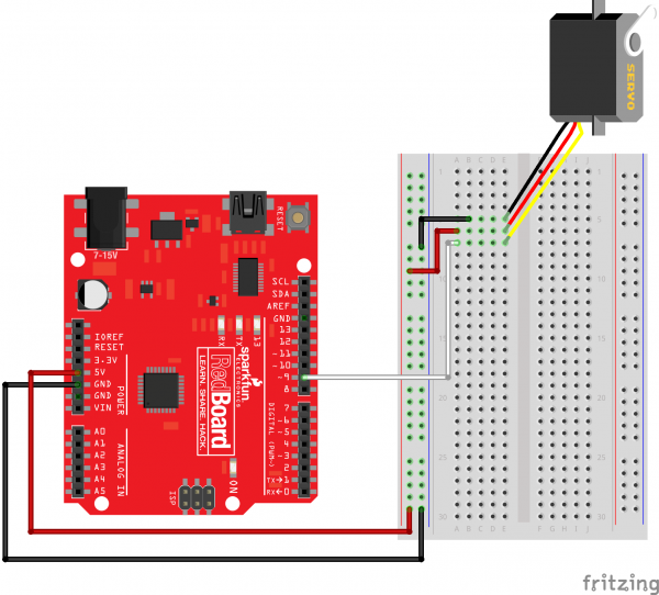
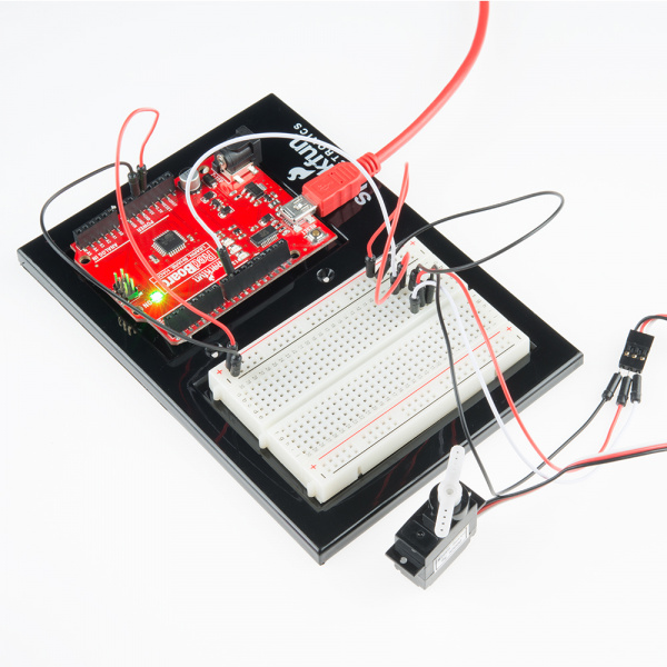
Ready to start hooking everything up? Check out the Fritzing diagram below, to see how everything is connected.
| Polarized Components | Pay special attention to the component’s markings indicating how to place it on the breadboard. Polarized components can only be connected to a circuit in one direction. |
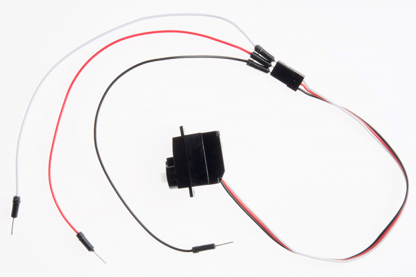
Connect 3x jumper wires to the female 3 pin header on the servo. This will make it easier to breadboard the servo.
Fritzing Diagram for RedBoard
Having a hard time seeing the circuit? Click on the Fritzing diagram to see a bigger image.
Run the Sketch
/*
SparkFun Inventor's Kit
Example sketch 08

SINGLE SERVO

  Sweep a servo back and forth through its full range of motion.

  A "servo", short for servomotor, is a motor that includes
  feedback circuitry that allows it to be commanded to move to
  specific positions. This one is very small, but larger servos
  are used extensively in robotics to control mechanical arms,
  hands, etc. You could use it to make a (tiny) robot arm,
  aircraft control surface, or anywhere something needs to be
  moved to specific positions.

Hardware connections:

  The servo has a cable attached to it with three wires.
  Because the cable ends in a socket, you can use jumper wires
  to connect between the Arduino and the servo. Just plug the
  jumper wires directly into the socket.

  Connect the RED wire (power) to 5 Volts (5V)
  Connect the WHITE wire (signal) to digital pin 9
  Connect the BLACK wire (ground) to ground (GND)

  Note that servos can use a lot of power, which can cause your
  Arduino to reset or behave erratically. If you're using large
  servos or many of them, it's best to provide them with their
  own separate 5V supply. See this Arduino Forum thread for info:
  http://www.arduino.cc/cgi-bin/yabb2/YaBB.pl?num=1239464763

This sketch was written by SparkFun Electronics,
with lots of help from the Arduino community.
This code is completely free for any use.
Visit http://learn.sparkfun.com/products/2 for SIK information.
Visit http://www.arduino.cc to learn about the Arduino.

Version 2.0 6/2012 MDG
*/


// If we had to write a sketch to control a servo from scratch,
// it would be a lot of work. Fortunately, others have done the
// hard work for you. We're going to include a "library"
// that has the functions needed to drive servos.

// A library is an set of additional functions you can add to
// your sketch. Numerous libraries are available for many uses,
// see http://arduino.cc/en/Reference/Libraries for information
// on the standard libraries, and Google for others. When you're
// using a new part, chances are someone has written a library
// for it.

#include <Servo.h>  // servo library

// Once you "include" a library, you'll have access to those
// functions. You can find a list of the functions in the servo
// library at: http://arduino.cc/en/Reference/Servo
// Most libraries also have example sketches you can load from
// the "file/examples" menu.

// Now we'll create a servo "object", called myservo. You should
// create one of these for each servo you want to control.
// You can control a maximum of twelve servos on the Uno
// using this library. (Other servo libraries may let you
// control more). Note that this library disables PWM on
// pins 9 and 10!

Servo servo1;  // servo control object


void setup()
{
  // We'll now "attach" the servo1 object to digital pin 9.
  // If you want to control more than one servo, attach more
  // servo objects to the desired pins (must be digital).

  // Attach tells the Arduino to begin sending control signals
  // to the servo. Servos require a continuous stream of control
  // signals, even if you're not currently moving them.
  // While the servo is being controlled, it will hold its
  // current position with some force. If you ever want to
  // release the servo (allowing it to be turned by hand),
  // you can call servo1.detach().

  servo1.attach(9);
}


void loop()
{
  int position;

  // To control a servo, you give it the angle you'd like it
  // to turn to. Servos cannot turn a full 360 degrees, but you
  // can tell it to move anywhere between 0 and 180 degrees.

  // Change position at full speed:

  servo1.write(90);    // Tell servo to go to 90 degrees

  delay(1000);         // Pause to get it time to move

  servo1.write(180);   // Tell servo to go to 180 degrees

  delay(1000);         // Pause to get it time to move

  servo1.write(0);     // Tell servo to go to 0 degrees

  delay(1000);         // Pause to get it time to move

  // Change position at a slower speed:

  // To slow down the servo's motion, we'll use a for() loop
  // to give it a bunch of intermediate positions, with 20ms
  // delays between them. You can change the step size to make
  // the servo slow down or speed up. Note that the servo can't
  // move faster than its full speed, and you won't be able
  // to update it any faster than every 20ms.

  // Tell servo to go to 180 degrees, stepping by two degrees

  for(position = 0; position < 180; position += 2)
  {
    servo1.write(position);  // Move to next position
    delay(20);               // Short pause to allow it to move
  }

  // Tell servo to go to 0 degrees, stepping by one degree

  for(position = 180; position >= 0; position -= 1)
  {
    servo1.write(position);  // Move to next position
    delay(20);               // Short pause to allow it to move
  }
}
Code To Note
#include <Servo.h>#include is a special “preprocessor” command that inserts a library (or any other file) into your sketch. You can type this command yourself, or choose an installed library from the “sketch / import library” menu.Servo servo1;servo1.attach(9);
The servo library adds new commands that let you control a servo. To prepare the Arduino to control a servo, you must first create a Servo “object” for each servo (here we’ve named it “servo1”), and then “attach” it to a digital pin (here we’re using pin 9).
servo1.write(180);
The servos in this kit don’t spin all the way around, but they can be commanded to move to a specific position. We use the servo library’s
write() command to move a servo to a specified number of degrees(0 to 180). Remember that the servo requires time to move, so give it a short delay() if necessary.What You Should See
You should see your servo motor move to various locations at several speeds. If the motor doesn’t move, check your connections and make sure you have verified and uploaded the code, or see the troubleshooting section.
Real World Application
Robotic arms you might see in an assembly line or sci-fi movie probably have servos in them.
Troubleshooting
Servo Not Twisting
Even with colored wires it is still shockingly easy to plug a servo in backward. This might be the case.
Still Not Working
A mistake we made a time or two was simply forgetting to connect the power (red and black wires) to +5 volts and ground.
Fits and Starts
If the servo begins moving then twitches, and there’s a flashing light on your RedBoard or Arduino Uno R3, the power supply you are using is not quite up to the challenge. Using a wall adapter instead of USB should solve this problem.
Adapted from Sparkfun Inventor Kit Experiential Guide
Want to save some time learning Arduino?
Join the thousands of awesome people to sign up for our
FREE Arduino Video Crash Course!
FREE Arduino Video Crash Course!


