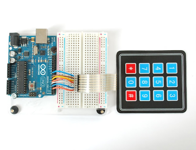
This mini project shows you how to read a 3x4 matrix keypad and display the results on a 7 segment display via a 74HC595 serial to parallel shift register.
Hardware
- Arduino
- Adafruits Membrane 3x4 Matrix Keypad
- 7 Seg LCD Display (common cathode is what I used)
- 74HC595
- 330 resistor
- hookup wire
- breadboard
Circuit:
Connect the keypad to the Arduino to match this image
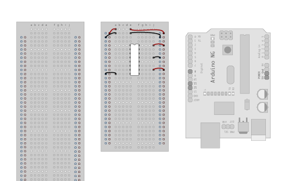
Connecting up the 74HC595
Make the following connections:
GND (pin 8) to ground,
Vcc (pin 16) to 5V
OE (pin 13) to ground
MR (pin 10) to 5V
This set up makes all of the output pins active and addressable all the time. The one flaw of this set up is that you end up with the lights turning on to their last state or something arbitrary every time you first power up the circuit before the program starts to run. You can get around this by controlling the MR and OE pins from your Arduino board too, but this way will work and leave you with more open pins.
Arduino Connections to 74HC595
DS (pin 14) to Ardunio DigitalPin 11 (blue wire)
SH_CP (pin 11) to to Ardunio DigitalPin 10 (yellow wire)
ST_CP (pin 12) to Ardunio DigitalPin 9 (green wire)
From now on those will be refered to as the dataPin, the clockPin and the latchPin respectively. Notice the 0.1"f capacitor on the latchPin, if you have some flicker when the latch pin pulses you can use a capacitor to even it out.
Connecting 7 Seg Dispay to 74HC595
SH_CP (pin 11) to to Ardunio DigitalPin 10 (yellow wire)
ST_CP (pin 12) to Ardunio DigitalPin 9 (green wire)
From now on those will be refered to as the dataPin, the clockPin and the latchPin respectively. Notice the 0.1"f capacitor on the latchPin, if you have some flicker when the latch pin pulses you can use a capacitor to even it out.

Connecting 7 Seg Dispay to 74HC595
I used a common cathode seven segment display which means the middle pin on the top (pin 9) and bottom (pin 3) of the display would be connected to ground via a 220ohm current limiting resistor (pins 3 and 9). Starting with D0 of the 74HC595 (pin 15) I connected to the dot segment on the 7 segment display, and followed around connecting D2 - D7 to the remaining segments.
I use trial and error to figure out what my bit map would be. You can look at the symbols array in the code and compare the bits being turned on with the segments that it takes to make that number. For example. to display a character number 1 on a seven segment display we need to turn on segments 'c' and 'b'. The bit pattern to do that is B00010010, so we can conclude that D1 connects to the c segment and D4 to the b (notice when making a 6 that D4 is off while D1 is on, that is how I knew D1 connects to the c segment and b to the D4)
Code
#include "Arduino.h"
#include "Keypad.h"

const byte ROWS = 4; //four rows
const byte COLS = 3; //three columns
char keys[ROWS][COLS] =
{
    {'1', '2', '3'},
    {'4', '5', '6'},
    {'7', '8', '9'},
    {'*', '0', '#'}
};
byte rowPins[ROWS] = {8, 7, 6, 5}; //connect to the row pinouts of the keypad
byte colPins[COLS] = {4, 3, 2}; //connect to the column pinouts of the keypad

Keypad keypad = Keypad( makeKeymap(keys), rowPins, colPins, ROWS, COLS );

//Pin connected to latch pin (ST_CP) of 74HC595
const int latchPin = 9;
//Pin connected to clock pin (SH_CP) of 74HC595
const int clockPin = 10;
////Pin connected to Data in (DS) of 74HC595
const int dataPin = 11;

const byte CHAR_COUNT = 10;

const byte symbols[CHAR_COUNT] =
{
    B01111110, // 0
    B00010010, // 1
    B10111100, // 2
    B10110110, // 3
    B11010010, // 4
    B11100110, // 5
    B11101110, // 6
    B00110010, // 7
    B11111110, // 8
    B11110110  // 9
};


void setup()
{
    //set pins to output because they are addressed in the main loop
    pinMode(latchPin, OUTPUT);
    pinMode(dataPin, OUTPUT);
    pinMode(clockPin, OUTPUT);
    Serial.begin(9600);
}

void loop()
{
    char key = keypad.getKey();

    if (key != NO_KEY)
    {
        Serial.println(key);
        Serial.println(symbols[key-48]);
        writeLeds(symbols[key - 48]);
    }

}


void writeLeds(byte pattern)
{
    // turn off the output so the pins don't light up
    // while you're shifting bits:
    digitalWrite(latchPin, LOW);

    // shift the bits out:
    shiftOut(dataPin, clockPin, MSBFIRST, pattern);

    // turn on the output so the LEDs can light up:
    digitalWrite(latchPin, HIGH);
}
Video

