Arduino GPS Clock

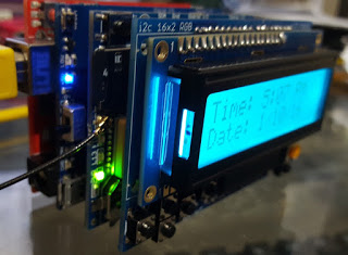
I built the Arduino GPS Clock by Tony DiCola over at Adafruit. The clock was very cool, setting it's time from the satellites, however, I soon started feeling like I was wasting my GPS shield by only using it to get time. So I decided to use the RGB LCD Shield which would allow me to display more information and be more interactive with the device. At the time of this writing I have four boards stacked. 1) Thearduino, 2) An Ad afruit PowerBoost Shield with a 2000ma Lipo Battery, 3) The Adafruit Ultimate GPS Logger Shield and 4) the Adafruit RGB LCD Shield.

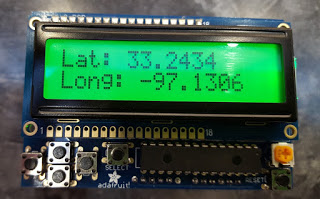
Having four boards stacked does make it bulky but I will be reducing that by dropping the Arduino Uno R3 board and replacing it's functionality with an Arduino Pro Mini placed in the prototype section of the GPS Logger Shield. On the software side I currently have it displaying the time and date on its initial screen. Other screens show "Latitude and Longitude", "Speed and Angle", Altitude and Satellites, then the Select button displays the message "This is a clock NOT a bomb. :-)
I plan to add some code to support logging GPS coordinates to the SD card. Then I would like to try and implement Ladyada's logger which is interrupt driven to log data. I would hope to accomplish a feature where background logging could be turned on and off. The user in the foreground could set flags that would mark spots as important for the back ground logger to flag so that it could be recognized later when importing the data to google maps or some other gps mapping system.
// Clock example using a seven segment display & GPS for time.
//
// Must have the Adafruit GPS library installed too!  See:
//   https://github.com/adafruit/Adafruit-GPS-Library
//
// Designed specifically to work with the Adafruit LED 7-Segment backpacks
// and ultimate GPS breakout/shield:
// ----> http://www.adafruit.com/products/881
// ----> http://www.adafruit.com/products/880
// ----> http://www.adafruit.com/products/879
// ----> http://www.adafruit.com/products/878
// ----> http://www.adafruit.com/products/746
//
// Adafruit invests time and resources providing this open source code,
// please support Adafruit and open-source hardware by purchasing
// products from Adafruit!
//
// Written by Tony DiCola for Adafruit Industries.
// Released under MIT a license: https://opensource.org/licenses/MIT
#include <SoftwareSerial.h>
#include <Wire.h>
#include "Adafruit_LEDBackpack.h"
#include "Adafruit_GFX.h"
#include "Adafruit_GPS.h"


// Set to false to display time in 12 hour format, or true to use 24 hour:
#define TIME_24_HOUR      false

// Offset the hours from UTC (universal time) to your local time by changing
// this value.  The GPS time will be in UTC so lookup the offset for your
// local time from a site like:
//   https://en.wikipedia.org/wiki/List_of_UTC_time_offsets
// This value, -7, will set the time to UTC-7 or Pacific Standard Time during
// daylight savings time.
#define HOUR_OFFSET       -6

// I2C address of the display.  Stick with the default address of 0x70
// unless you've changed the address jumpers on the back of the display.
#define DISPLAY_ADDRESS   0x70


// Create display and GPS objects.  These are global variables that
// can be accessed from both the setup and loop function below.
Adafruit_7segment clockDisplay = Adafruit_7segment();

SoftwareSerial gpsSerial(8, 7);  // GPS breakout/shield will use a
// software serial connection with
// TX = pin 8 and RX = pin 7.

Adafruit_GPS gps(&gpsSerial);


void setup()
{
    // Setup function runs once at startup to initialize the display and GPS.

    // Setup Serial port to print debug output.
    Serial.begin(115200);
    Serial.println("Clock starting!");

    // Setup the display.
    clockDisplay.begin(DISPLAY_ADDRESS);

    // Setup the GPS using a 9600 baud connection (the default for most
    // GPS modules).
    gps.begin(9600);

    // Configure GPS to onlu output minimum data (location, time, fix).
    gps.sendCommand(PMTK_SET_NMEA_OUTPUT_RMCONLY);

    // Use a 1 hz, once a second, update rate.
    gps.sendCommand(PMTK_SET_NMEA_UPDATE_1HZ);

    // Enable the interrupt to parse GPS data.
    enableGPSInterrupt();
}

void loop()
{
    // Loop function runs over and over again to implement the clock logic.

    // Check if GPS has new data and parse it.
    if (gps.newNMEAreceived())
    {
        gps.parse(gps.lastNMEA());
    }

    // Grab the current hours, minutes, seconds from the GPS.
    // This will only be set once the GPS has a fix!  Make sure to add
    // a coin cell battery so the GPS will save the time between power-up/down.
    int hours = gps.hour + HOUR_OFFSET;  // Add hour offset to convert from UTC
    // to local time.
    // Handle when UTC + offset wraps around to a negative or > 23 value.
    if (hours < 0)
    {
        hours = 24 + hours;
    }
    if (hours > 23)
    {
        hours = 24 - hours;
    }
    int minutes = gps.minute;
    int seconds = gps.seconds;

    // Show the time on the display by turning it into a numeric
    // value, like 3:30 turns into 330, by multiplying the hour by
    // 100 and then adding the minutes.
    int displayValue = hours * 100 + minutes;

    // Do 24 hour to 12 hour format conversion when required.
    if (!TIME_24_HOUR)
    {
        // Handle when hours are past 12 by subtracting 12 hours (1200 value).
        if (hours > 12)
        {
            displayValue -= 1200;
        }
        // Handle hour 0 (midnight) being shown as 12.
        else if (hours == 0)
        {
            displayValue += 1200;
        }
    }

    // Now print the time value to the display.
    clockDisplay.print(displayValue, DEC);

    // Add zero padding when in 24 hour mode and it's midnight.
    // In this case the print function above won't have leading 0's
    // which can look confusing.  Go in and explicitly add these zeros.
    if (TIME_24_HOUR && hours == 0)
    {
        // Pad hour 0.
        clockDisplay.writeDigitNum(1, 0);
        // Also pad when the 10's minute is 0 and should be padded.
        if (minutes < 10)
        {
            clockDisplay.writeDigitNum(2, 0);
        }
    }

    // Blink the colon by turning it on every even second and off
    // every odd second.  The modulus operator is very handy here to
    // check if a value is even (modulus 2 equals 0) or odd (modulus 2
    // equals 1).
    clockDisplay.drawColon(seconds % 2 == 0);

    // Now push out to the display the new values that were set above.
    clockDisplay.writeDisplay();

    // Loop code is finished, it will jump back to the start of the loop
    // function again! Don't add any delays because the parsing needs to
    // happen all the time!
}

SIGNAL(TIMER0_COMPA_vect)
{
    // Use a timer interrupt once a millisecond to check for new GPS data.
    // This piggybacks on Arduino's internal clock timer for the millis()
    // function.
    gps.read();
}

void enableGPSInterrupt()
{
    // Function to enable the timer interrupt that will parse GPS data.
    // Timer0 is already used for millis() - we'll just interrupt somewhere
    // in the middle and call the "Compare A" function above
    OCR0A = 0xAF;
    TIMSK0 |= _BV(OCIE0A);
}
Lots to learn and try on this project.
UPDATE 4/10/16
The Arduino Pro Mini was put in place eliminating the need of the UNO R3.
Comments
comments powered by Disqus