Creating a Four Digit Display Using 74HC595 Shift Registers
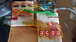
My last experiment was with the three 74HC595s I was using to create the Knightrider effect on 24 leds. In this experiment I am going to add another 74HC595 and use all four to control four common-cathode seven-segment LED displays.
To duplicate this setup you will need the following hardware:
- Four 74HC595 shift registers
- Four common-cathode seven-segment LED displays
- Thirty Two 560 Ohm Resistors.
- A large breadboard or several small ones connected together
- Various connecting wires
- Arduino UNO
Connections from Arduino in my setup
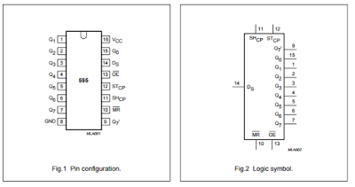
Pin 12 of the Arduino goes to pin 5 (the latch pin) on all of the 74HC595 shift registers. When data is shifted out in serial to the shift registers this pin is first taken low then brought back high once the data has been shifted out and needs to be presented to the outputs of the shift registers.
Pin 11 of the Arduino goes to pin 6 on all of the 74HC595 shift registers. This pin is clocked for each bit that is shifted in. This pin is used by the ShiftOut() library function to clock data into the shift registers.
Pin 14 of the Arduino is being used as the Serial Data Input to the shift registers.
In order for the serial data to flow to all four of the shift regisers, pin 9 of shift register 1 (my least significant digit, holding the ones position) will connect to pin 14 of shift register 2 (digit holding the 10's position). Pin 9 of shift register 2 will feed into pin 14 of shift register 3 (100's digit) and pin 9 of shift register 3 will feed into pin 14 of shift register 4 (1,000's digit).
Anytime I update the display it will involve four calls to the
ShiftOut() routine:
digitalWrite(latchPin, LOW);
shiftOut(dataPin, clockPin, LSBFIRST, digits[digit3]);
shiftOut(dataPin, clockPin, LSBFIRST, digits[digit2]);
shiftOut(dataPin, clockPin, LSBFIRST, digits[digit1]);
shiftOut(dataPin, clockPin, LSBFIRST, digits[digit0]);
digitalWrite(latchPin, HIGH);
Connections to 7 Segment Display
LED pins A through G connect to pins Q0 through Q6 and DP connects to Q7 via current limiting resistors

Wiring the Display
Each 7 segment display is going to have 8 resistors associated with it. I placed those 8 above the display on the breadboard and connected them to the 7 segment in the following order:
DP (pin5), G (pin 10), F (pin9), E (pin 1), D (pin 2), C (pin 4), B (pin 6), A (pin 7).
Once I completed that wiring you might consider applying power to the board and testing by jumpering 5 volts to each resistor and confirming that the appropriate segment lights on your display.
Now that the resistors are in place and connected to the 7 segment displays you can connect the shift registers. Each 7 segment display is being driven by it's own shift register. Following the order laid out for the 7 segment display you will connect Q7 to the resistor on DP, Q6 to the resistor on G, Q5 to F, Q4 to E, Q3 to D, Q2 to C, Q1 to B and Q0 to A.
NOTE: A more practical way to have a 7 segment display would be using an Adafruit 0.56 4-digit 7-Segment Display w/I2C backpack and only using two pins on the Arduino. The backpack also multiplexes the displays so the current requirements are much lower. This experiment is an exercise in using the shift registers that were already breadboarded. Here is a video of the display counting 0 through 13,000 with no delay between counts. Once the count goes over 9,999 it will display dashes.
Here is the code I use to test the display. I have it display dashes if the number is above 9,999, or out of range:

David Riewe
Published
Tue 17 November 2015
Comments
comments powered by Disqus